485 serial port communication has basically become a must-have communication method in the field of industrial control. No matter it is PLC, DCS, large to large equipment, or as small as a single-chip microcomputer, they basically all have the communication function of 485. 485 communication only defines the standard of the hardware interface, as for what kind of protocol runs on the hardware, each device manufacturer will be somewhat different.
The protocol we may see the most is MODBUS_RTU. The ins and outs of the protocol will not be studied, we will only do a communication test. Because it is often necessary to use the MODBUS_RTU communication method to exchange data between the instrument and the controller. Some time ago, there happened to be a flow meter that needed to communicate with 200Smart. It is also the first time for me to use 200Smart for serial communication. Due to various reasons such as the epidemic, it is more difficult to test on site. So I want to test the serial communication and the working process of the program in the place where I live.
1. Hardware preparation
First of all, I prepared a 200Smart, the specific model is the simplest one of SR20. Then prepare a USB to 485 communication line or communication board. Another thing is to prepare a 9-pin DB connector (that is, a male head). There are solder-free ones on the Internet, which are more convenient to use and not expensive.
2. Software preparation
STEP 7-MicroWIN SMART programming software is definitely necessary, and there is software for simulating the slave station on the computer. The most common are Modbus Slave and ModSim32. I still prefer to use ModSim32, which is purely a personal habit, and I also use ModSim32 this time.
3. Auxiliary materials
Switches, network cables, mobile phone charging cables, and of course you need to buy a small screwdriver.
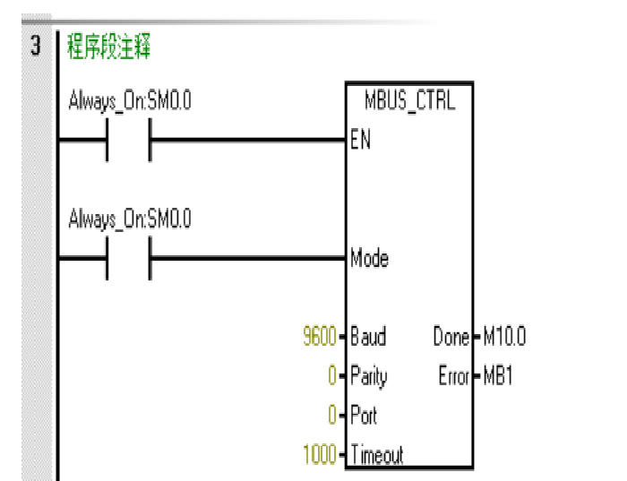
200Smart has two serial communication libraries, one is the master station and the other is the slave station. This time, 200Smart is used as the master station.1、Modbus RTU 主站初始化梯形图

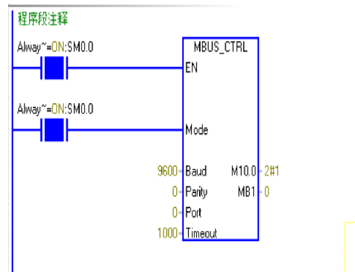
Baud baud rate, set according to the actual situation. Parity check. Port port, 0 represents the serial port that comes with the CPU body. Timeout timeout, the master waits for the response time of the slave. Done initialization is complete, this bit will be automatically set to 1, Error error code.
Actual screenshot of the program running.
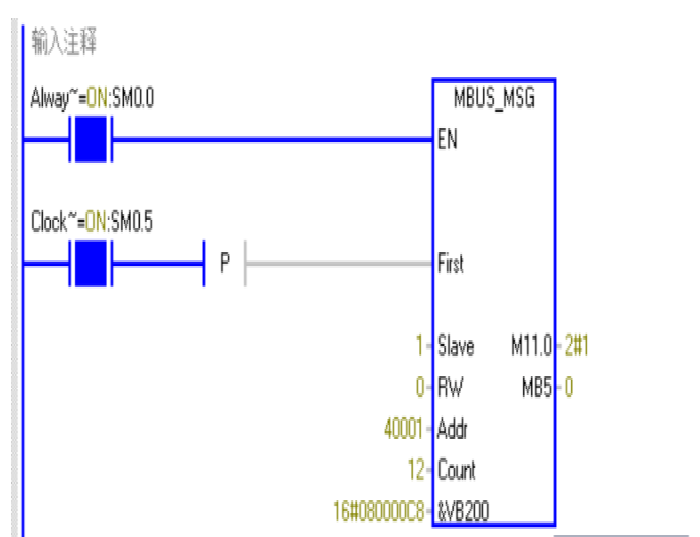
2. Modbus RTU master read and write subroutine MBUS_MSG
There are many introductions on the Internet. I also copied it, but there is a place in it that I still need to talk about. The Count is to define how many registers to read from the slave station. The number of registers read cannot be larger than the number provided by the slave station, otherwise there will be Error error code 102 report it. I think it is very important to read the error code to determine the error point in the communication process

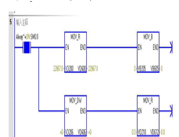
3. Data processing
In the above program, if the reading and writing function is completed, M11.0 is 1, and the error code is 0, indicating that the communication function is normal. There is a big flaw, even if the communication is normal, there is no indicator light on the 200Smart body, which is very bad. The small board communication used by 1200PLC will see the blinking of the indicator light, which can give some hints. Therefore, it is recommended to use a communication board with indicator lights to facilitate debugging when doing communication tests. After the communication is successful, the read data must be processed. The data is generally a floating point number or a long integer. Storage types VD and VB, DW.
The instructions used are MOV_R, MOV_B, MOV_DW. MOV_R converts floating-point numbers, MOV_B converts integers, and MOV_DW converts long integers. details as follows.

Run ModSim32 on the computer to simulate the slave station to respond to the data read from the master station.
1. RTU setting of ModSim32
The parameters are mainly baud rate, data bits, stop bits, and parity. These parameters are consistent with the MBUS_CTRL configuration of 200Smart. After setting the communication parameters, confirm

Through the above-mentioned simulation test of simulating 485 communication, there are mainly the following points:
(1) The PLC side is the setting of the serial communication command and the communication trigger, especially the communication trigger is a rising edge pulse, which is generally no problem. The most critical point is that 200Smart does not have a communication indicator light, which brings a lot of trouble to debugging. Sometimes the settings are correct, but the data display is not correct, and you will suspect a setting problem and take some detours.
(2) Another is the wiring problem. The serial port of the CPU on the 200Smart uses pins 3 and 8. I was not sure at first, so I asked Master Jiejie, haha. Sometimes A and B of 485 may be reversed, so try another.
(3) Another point is that it is better to use a communication board, preferably with a 485 communication indicator light. If you use some USB to 485 cables bought online, they are all for the sake of saving money, without any indicator lights, which will bring a lot of trouble to the communication test.
(4) The ID address and register type of ModSim32 must be consistent with those of the PLC. In some cases, the data type is incorrect and data overflow occurs. Debugging for the first time can still cause trouble. The data display format should also try more. As long as you see that the status of the communication indicator is normal, it means that the hardware interface is correct, and the rest is the data type.
(5) Another point is the conversion instructions in 200Smart, which must be distinguished as floating point numbers, integers, and long integers. This is related to the length of the memory. If the wrong length is selected, the converted data will also be messy. It may be seen at a glance after more debugging, but the first debugging will still delay a lot of time. Basically that's all, try more during debugging, do some homework in advance, the problem is not big. Tried, failed, tried again, summed up, succeeded.


