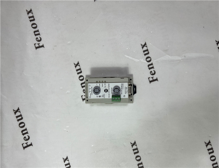
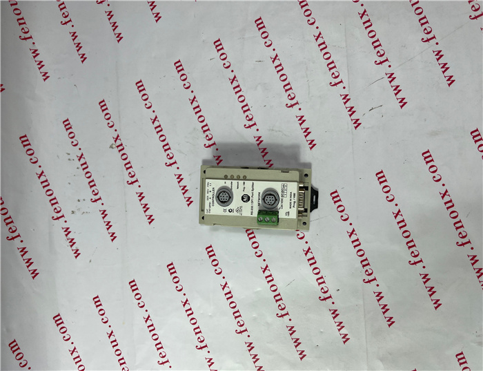
Brand: Allen Bradley
Model number: 1408-EM3A-ENT
Colour:new
Warranty: 12 months
Lead Time:3-day working day
Country of origin: USA Price: Please contact us
Product weight:0.11kg
Shipping Port: Xiamen, China
Payment: Bank of Chicago, Bank of Singapore
Express cooperation: fedex, DHL, UPS and your express account
Service: Professional Sales provides 24 hours /7 days online service
Description:
Panel Mounting Procedure Using Modules as a Template
The following procedure allows you to use the assembled modules as a
template for drilling holes in the panel. If you have sophisticated panel
mounting equipment, you can use the dimensional template provided on
page 6. Due to module mounting hole tolerance, it is important to follow
these procedures:
1. On a clean work surface, assemble no more than three modules.
2. Using the assembled modules as a template, carefully mark the center of
all module-mounting holes on the panel.
3. Return the assembled modules to the clean work surface, including any
previously mounted modules.
4. Drill and tap the mounting holes for the recommended M4 or #8 screw.
5. Place the modules back on the panel, and check for proper hole
alignment.
6. Attach the modules to the panel using the mounting screws.
7. Repeat steps 1 to 6 for any remaining modules.
DIN Rail Mounting
The module can be mounted using the following DIN rails: 35 x 7.5 mm
(EN 50 022 - 35 x 7.5) or 35 x 15 mm (EN 50 022 - 35 x 15).
Before mounting the module on a DIN rail, close the DIN rail latches. Press
the DIN rail mounting area of the module ag
Consider the following when wiring your system:
• All module commons (ANLG COM) are connected in the analog module.
The analog common (ANLG COM) is not connected to earth ground
inside the module.
• Do not use the analog module’s NC terminals as connection points.
• Channels are not isolated from each other.
• Use Belden™ 8761, or equivalent, shielded wire.
• Under normal conditions, the drain wire and shield junction must be
connected to earth ground, via a panel or DIN rail mounting screw at
the analog I/O module end. Keep the shield connection to ground as
short as possible.(1)
• To ensure optimum accuracy, limit overall cable impedance by keeping
your cable as short as possible. Locate the I/O system as close to your
sensors or actuators as your application will permit.
• Voltage outputs (Vout 0+ and Vout 1+) of the 1769-OF2 module are
referenced to ANLG COM. Load resistance for a voltage output channel
must be equal to or greater than 1K Ω .
• Current outputs (Iout 0+ and Iout 1+) of the 1769-OF2 module source
current that returns to ANLG COM. Load resistance for a current output
channel must remain between 0 and 500 Ω

Shipping Port: Xiamen, China
Payment: Bank of Chicago, Bank of Singapore
Express cooperation: fedex, DHL, UPS and your express account
Service: Professional Sales provides 24 hours /7 days online service
Related products:
20F11ND027AA0NNNNN
2711-T5A2L1
2711PC-T6M20D
1794-IR8
1756-RM2
1794-OB32P
1794-IE12