Brand:Allen-Bradley
Model number:1769-IR6
Colour:new
Warranty: 12 months
Lead Time:3-day working day
Country of origin: USA Price: Please contact us
Product weight:0.12kg
Shipping Port: Xiamen, China
Payment: Bank of Chicago, Bank of Singapore
Express cooperation: fedex, DHL, UPS and your express account
Service: Professional Sales provides 24 hours /7 days online service
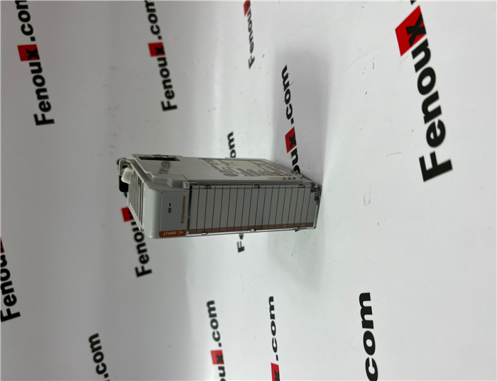
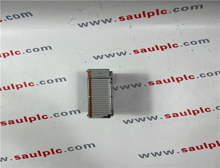
Module Overview :
The 1769-IR6 module receives and stores digitally converted analog data from RTDs or other resistance inputs, such as potentiometers. The module supports connections from any combination of up to 6 RTDs or other resistance inputs. See the input specifications on page 20 for supported RTD and resistance types, their associated temperature ranges, and the analog input signal ranges that each channel supports. Each of the 6 input channels is individually configurable for a specific input device and provides open- or short-circuit and over- or under-range indication.
System Assembly
The module can be attached to the controller or an adjacent I/O module before or
after mounting. For mounting instructions, see “Panel Mounting” on page 6, or
“DIN Rail Mounting” on page 7. To work with a system that is already mounted, see
“Replacing a Single Module within a System” on page 7.
The following procedure shows you how to assemble the Compact I/O system
1. Disconnect power.
2. Check that the bus lever of the module to be installed is in the unlocked
(fully right) position.
3. Use the upper and lower tongue-and-groove slots (1) to secure the modules
together (or to a controller).
4. Move the module back along the tongue-and-groove slots until the bus
connectors (2) line up with each other.
5. Push the bus lever back slightly to clear the positioning tab (3). Use your
fingers or a small screwdriver.
The following procedure allows you to use the assembled modules as a template
for drilling holes in the panel. If you have sophisticated panel mounting equipment,
you can use the dimensional template provided on page 6. Due to module
mounting hole tolerance, it is important to follow these procedures:
1. On a clean work surface, assemble no more than three modules.
2. Using the assembled modules as a template, carefully mark the center of all
module-mounting holes on the panel.
3. Return the assembled modules to the clean work surface, including any
previously mounted modules.
4. Drill and tap the mounting holes for the recommended M4 or #8 screw.
5. Place the modules back on the panel and check for proper hole alignment.
6. Attach the modules to the panel using the mounting screws.
7. Repeat steps 1 to 6 for any remaining modules.
NOTE If mounting more modules, mount only the last one of this
group and put the others aside. This reduces remounting time
during drilling and tapping of the next group.


Shipping Port: Xiamen, China
Payment: Bank of Chicago, Bank of Singapore
Express cooperation: fedex, DHL, UPS and your express account
Service: Professional Sales provides 24 hours /7 days online service
Relevant models:
1756-N2
1756-OA16I
1756-OB16E
1756-OF6CI
1756-OW16I
1756-PA75
1756-PA75B
1756-PB75
1756-RM
1762-OW8
1769-IF8
1769-IT6
1769-L32E-QEFC1B
1769-L33ER
1769-OW16
1771-IFE
1783-ETAP2F
1783-RMS10T
1783-SFP1GSX
1783-SFP100LX
1783-US16T
2711-B5A5
2711P-RDT10C
2711P-RN15S