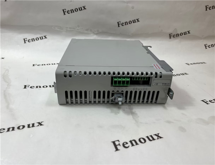
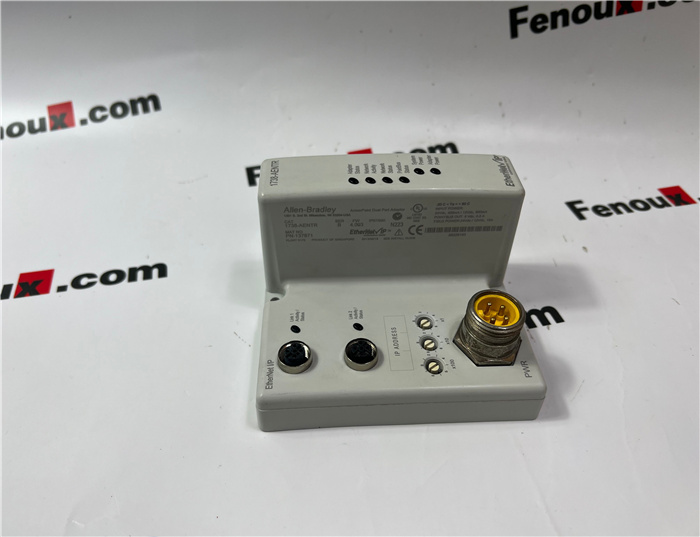
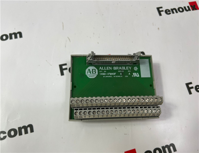
Brand: Allen Bradley
Model number:2094-XL75S-C1
Colour:new
Warranty: 12 months
Lead Time:3-day working day
Country of origin: USA Price: Please contact us
Product weight:0.42kg
Shipping Port: Xiamen, China
Payment: Bank of Chicago, Bank of Singapore
Express cooperation: fedex, DHL, UPS and your express account
Service: Professional Sales provides 24 hours /7 days online service
Description:
To ground the switch to earth ground, follow these steps. Be sure to follow any grounding requirements at your site.
1. To remove the ground screw from the front panel of the switch, use a Phillips screwdriver or a ratcheting torque screwdriver with a Phillips head.
Store the ground screw for later use.
2. Use the guidelines from the manufacturer to determine the wire length to be stripped.
3. Insert the ground wire into the ring terminal lug and use a crimping tool to crimp the terminal to the wire.
If you are using two ring terminals, repeat this action for the second ring terminal.
4. Slide the ground screw through the terminal.
5. Insert the ground screw into the functional ground screw opening on the front panel.
6. Use a ratcheting torque screwdriver to tighten the ground screws and ring terminal lugs to the switch front panel to 0.4 Nm (3.5 inlb).
Do not exceed the recommended torque.
7. Attach the other end of the ground wire to a grounded bare metal surface, such as a ground bus, a grounded DIN rail, or a grounded bare rack.
. Measure a length of 0.82…0.52 mm2
(18…20 AWG) copper wire long enough to connect to the DC power source.
2. Using an 18-gauge wire-stripping tool, strip each of the two wires to 6.3 mm (0.25 in.) ± 0.5 mm (0.02 in.).
Do not strip more than 6.8 mm (0.27 in.) of insulation from the wire. Stripping more than the recommended amount of wire can leave wire exposed after installation.
3. Locate the power connector.
Application Power Input per Port Power Consumption Allen-Bradley® Products
PoE only
IEEE 802.3af 44…57V DC (48V DC, nom) 15.4 W, max Switched mode power supplies: • 1606-XL Standard • 1606-XLE Essential
• 1606-XLP Compact • 1606-XLS Performance
PoE and PoE +
IEEE 802.3 at Type 2 50…57V DC (54V DC, nom) 15.4 W, max for PoE
30 W, max for PoE+
IN1—External Device Connection
1.REF—External Device Connection 2
12 Rockwell Automation Publication 1783-IN016C-EN-P - August 2022
Stratix 5700 Ethernet Managed Switches Installation Instructions
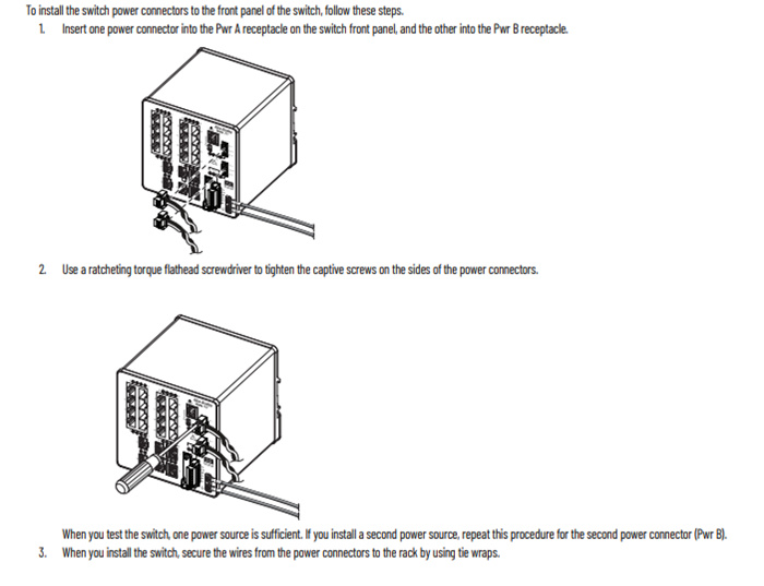
4. Insert the exposed part of the positive wire into the DC+ connection and the exposed part of the return wire into the DC- connection.
Make sure that you cannot see any wire lead. Only wire with insulation can extend from the connector.
5. Use a ratcheting-torque screwdriver to torque the captive screws of the power connector to 0.23 N•m (2.0 in•lb).
6. Connect the other end of the positive wire (the one connected to DC+) to the positive terminal on the DC power source.
7. Connect the other end of the return wire (the one connected to DC-) to the return terminal on the DC power source
Shipping Port: Xiamen, China
Payment: Bank of Chicago, Bank of Singapore
Express cooperation: fedex, DHL, UPS and your express account
Service: Professional Sales provides 24 hours /7 days online service
Related products:
20F11ND027AA0NNNNN
2711-T5A2L1
2711PC-T6M20D
1794-IR8
1756-RM2
1794-OB32P
1794-IE12
22B-D2P3N104
1794-OE12


