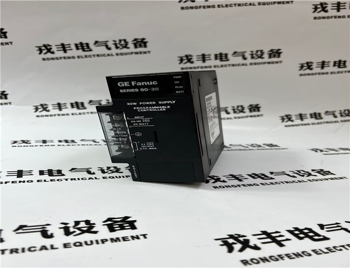
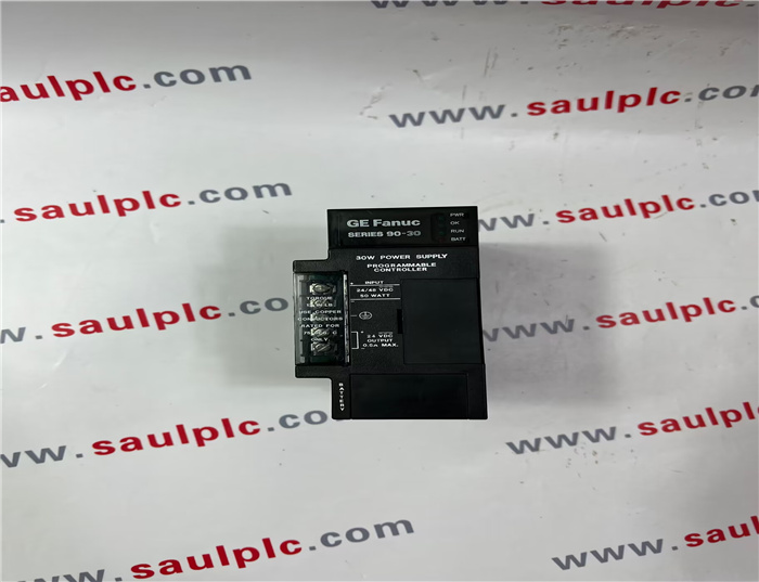
Brand:GE
Model number:IC693PWR322E
Colour:new
Warranty: 12 months
Lead Time:3-day working day
Country of origin: USA Price: Please contact us
Product weight:0.42kg
Shipping Port: Xiamen, China
Payment: Bank of Chicago, Bank of Singapore
Express cooperation: fedex, DHL, UPS and your express account
Service: Professional Sales provides 24 hours /7 days online service
Description:
Field Wiring Connections and
Installation Information
DC Power Source Connections
The + and – wires from the 12 VDC power source
connect to the top two protected terminals on the powers
supply terminal board. Connect the + wire to the top
terminal and the – wire to the second terminal. A
connection diagram is printed on the front of the power
supply module next to the terminal board.
Isolated 24 VDC Supply
The bottom two terminal board terminals provide
connections to the Isolated 24 VDC output. This output
can be used to provide power for input circuits for 24
VDC Input Modules (within the 15 watt limitation of this
output). This is useful because power switched to input
points must be supplied from a source external to the
IC693 input modules.
Wire Connection information
• Each terminal can accept solid or stranded wires, but,
if using two wires on one terminal, the wires should
be the same size and type.
• The suggested torque for the power supply terminal
board screws is 12 in-lbs. (1.36 Nm).
• Use one AWG #14 (2.1 mm2
) or two AWG #16 (1.3
mm2
) copper conductors, rated for 75 degrees C (167
degrees F) only, per terminal board terminal.
Input Overvoltage Protection Devices
The input overvoltage protection devices are connected
internally to pin 4 of the terminal board. This pin is
normally connected to pin 3 (frame ground) via a factoryinstalled
jumper strap. If a Hi-Pot test is to be performed
on this supply, the jumper strap must be removed during
the test so that the overvoltage protection devices are not
damaged. After testing, replace the jumper strap to
restore overvoltage protection during normal operation.
Use These Steps for Calculating
Input Power Requirements
• Determine total output load from typical
specifications listed for individual modules in the
IC693 PLC Installation and Hardware Manual.
• Multiply the total output load, determined in the
previous step, by 1.5 to determine input power value.
• Divide the input power by the operating source
voltage to determine the input current requirement.
Since operating source voltage may vary, use the
lowest measured or estimated input voltage to
determine the maximum input current.
• Allow for start-up surge current requirements.
• Allow margin (10% to 20%) for variation.

Shipping Port: Xiamen, China
Payment: Bank of Chicago, Bank of Singapore
Express cooperation: fedex, DHL, UPS and your express account
Service: Professional Sales provides 24 hours /7 days online service
Related products:
04220FL11232A
8851-LC-MT
IC660EBS103
IC695CPE330
IC697CPX928-FE
IC695ACC402
IC200ALG230H
IC200MDL650K
IC660BBD101
IC693ALG223C
IC693ALG223D
IC693CBL300B
IC693CHS393G
IC693CPU313J
IC693CHS397M
IC693CPU350-DG
IC693CPU372